Arduino BLE
Communicate With Arduino Over BLE. This is an experimental example, that shows how to communicate with an Arduino board equipped with the Bluetooth Low Energy (BLE) shield.

Source code
You can browse the source code for this example at the Evothings GitHub repository
The file index.html is the entry point of the app.
The file arduinoble.ino contains the Arduino BLE server that communicates with the app.
What you need
This example runs in Evothings Viewer on Android or iOS.
You need to run the example in Evothings Viewer. Alternatively, you can make a Cordova application if you wish to distribute the app. You then need to include the Cordova plugin com.evothings.ble. Read more in the documentation of the Evothings Viewer.
An iOS device or an Android device with support for Bluetooth 4.0 (which includes BLE) is required. In addition Android 4.3 or later is needed. Please note that BLE support on Android is still not fully mature. As a result, you may experience difficulties running this example. If the app stops working, restart Evothings Viewer and/or reset Bluetooth on the device.
You need and Arduino board with a BLE shield.
For the Arduino setup, you need:
- LED
- Resistor 220 Ohm
- Potentiometer
- BLE shield
- Install BLE libraries in the Arduino IDE library folder. Go to the page Getting Started with BLE Shield and follow the instructions regarding libraries setup.
Sketch
This is a sketch of a board configured to work with this example. Please observe that a Bluetooth LE shield, like the RedBearLab BLE Shield is required and would sit on top of the Arduino in the illustration, but is currently missing from this sketch. However, the pins pass straight through, while this sketch is meant to show you the wiring for the example.
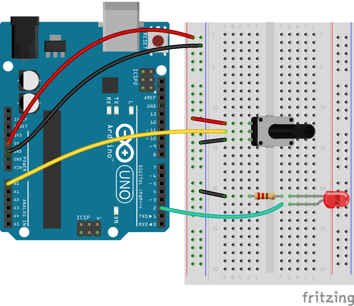
The ON & OFF buttons controls digital pin 2 on the Arduino, here connected to a LED (long leg is the anode - connect to plus - and short one the cathode to be attached to minus if relevant or ground (GND pin). The plot also demonstrates reading an input signal from analog pin A0 - which is here connected to a variable resistor (potentiometer). Please experiment with your own circuits and let us know how cool they are!